Pcbnew : drawing arcs with start / end points first.
Description
When drawing an arc in Pcbnew, we first select the center of the arc, then two points. Sometimes, we know where we want the arc to start and to end, but the radius is not the main concern.
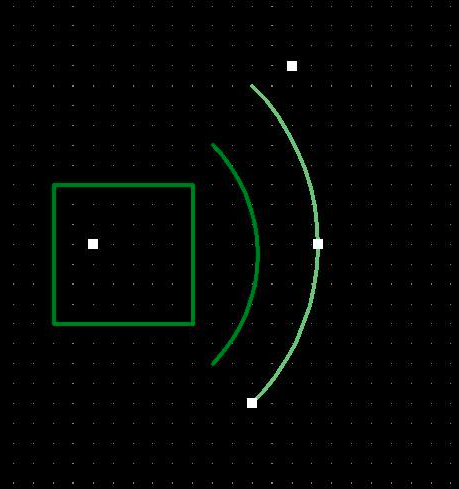
Therefore, I think having an alternate drawing method for drawing arcs would be great. Using this method, the user would first select two points that define the arc start/ end points, A and B, and then would change the curvature of the arc, by moving the center of the arc, C.
I think this would be helpful in some cases, including if a trace needs to follow a complex board outline. ( IFAIK, we can't snap the end point to a track)
In this image, the position of C is not that easy to guess, so the arc can meet both A and B correctly:

Steps to reproduce
KiCad Version
Application: Pcbnew

Version: 5.99.0-unknown-93e3268~102~ubuntu20.04.1, release build

Libraries:
	wxWidgets 3.0.4
	libcurl/7.68.0 OpenSSL/1.1.1f zlib/1.2.11 brotli/1.0.7 libidn2/2.2.0 libpsl/0.21.0 (+libidn2/2.2.0) libssh/0.9.3/openssl/zlib nghttp2/1.40.0 librtmp/2.3

Platform: Linux 5.4.0-42-generic x86_64, 64 bit, Little endian, wxGTK

Build Info:
	Date: Aug  1 2020 10:17:29
	wxWidgets: 3.0.4 (wchar_t,wx containers,compatible with 2.8) GTK+ 3.24
	Boost: 1.71.0
	OCE: 6.9.1
	Curl: 7.68.0
	ngspice: 31
	Compiler: GCC 9.3.0 with C++ ABI 1013

Build settings:
	KICAD_SCRIPTING=ON
	KICAD_SCRIPTING_MODULES=ON
	KICAD_SCRIPTING_PYTHON3=ON
	KICAD_SCRIPTING_WXPYTHON=ON
	KICAD_SCRIPTING_WXPYTHON_PHOENIX=ON
	KICAD_SCRIPTING_ACTION_MENU=ON
	BUILD_GITHUB_PLUGIN=ON
	KICAD_USE_OCE=ON
	KICAD_SPICE=ON
Activity
added priorityundecided statusnew labels
Therefore, I think having an alternate drawing method for drawing arcs would be great.
I second that. However, I'd like to add that having options for A and B to be tangential would be important for maintaining a proper shape constrained by two lines it connects to.
In (Cadsoft) Eagle, trace corners can be mitered, but even there the angle is fixed once created, where it should result from the included angle between the two lines. So creating arcs will be governed by different sets of constraints.
Here's another concept from Autodesk Inventor providing both arcs constructed with various reference points, as well as Fillet.
 Edited by MisterHW
We support beziers actually, just don't have good editing tools for them yet. But, this is not a bezier, it's just setting the arc center point to the one point where the ends of the arc will be tangent to the segments that share start/end points with the arc start/end points. This requires some code that doesn't exist yet (unless @twlostow has some in a branch somewhere) because we need to start considering the segments that the arc is touching in addition to the arc itself when drawing.
Nobody is working on parametric fillets right now, I think. There was discussion of non-parametric fillets, i.e. a tool where you click a corner and it would insert an appropriate arc and shorten the line segments, and in that case it would just be stored as lines and an arc just as if you manually drew the fillet.

@MisterHW IIRC, the rounded track feature is supposed to be the base for fillet : #4742
@craftyjon If we want to be tangent to both the beginning and the end of the arc, there are some cases where an arc won't work I think
Here, I think there is no way for an arc (based on a circle) to be tangent with both tracks.
 Edited by Fabien Corona
rounded track feature is supposed to be the base for fillet
The rounded track feature that is being developed is not the same as parametric fillets like are available in mechanical CAD tools. It just allows you to insert arcs at the same time as straight tracks, not apply fillets to a bunch of existing tracks without rounded corners.
If we look at the screenshot above (with two concentric cirles) and suppose we need to create an arc between them, it doesn't indeed work at all if we have to first make the straight lines end at the right spots. It would be counterproductive to first manually tune the lines. Actually, with non n*45deg angles it would become practically impossible.
The only reasonable way for it the work is to have imaginary infinite lines, use them as the tangents, add the arc (with some known radius) and lengthen or shorten the straight lines automatically. The only thing which the user needs is to select two lines (tracks or whatever), select "add fillet/arc" action and give the radius in one way or another.
IMO it would be possible to have a fillet tool which could handle all (imaginary) crossing lines as having a fillet, whether it has radius 0 or something else, and just change the radius WYSIWYG. It wouldn't even be relevant whether there's internally two lines and an arc or two lines with a fillet property.
But this is completely different task than drawing an arc with start/end points.
Edited by Eeli Kaikkonen-
I was curious, so I share it if anyone is interested in the two concentric circles problem. Note that point D is not guaranteed to be one the grid. So IMO, the added straight line should be on a group with the arc. In my calculations, I considered the track with point A should move (because AC < BC ) Hence the two regions where B can't be located.
This way, the arc would be tangential to both tracks. But this needs !325 (merged) so the center / start / end define the arc, and not center/ start / angle.

Nice work. In mechanical CAD terms, it's all about having the proper constraints driving the geometric construction. During arc editing, a line collinear to the corresponding trace segment (with 0 offset) is used, and one end point is coincident with that line, while the arc is tangential (the arc center is on a normal through the coincident point).
Don't worry too much about finding the one proper description for an arc - there are multiple unique ones (check out https://www.math10.com/en/geometry/geogebra/fullscreen.html which hopefully also comes in handy with the illustrations).

I think ultimately one could switch between different modes using a popup menu on right-click?

Not being on the grid also seems like a lesser issue. The polygon drawing tool also suffers from center handles that get snapped to grid, messing up the two segment endpoint coordinates, while the center handles could just translate them in grid increments (by storing and subtracting the modulus on mousedown). The same might apply here.
Edited by MisterHW-
The popup menu you have shown is I think one of the best way to do it.
However, as for the grid, if an arc is on a copper layer ( like a manual curved trace ), the start and end points should be on the grid I think, as they would connect to traces.
Edited by Fabien Corona 
I think ultimately one could switch between different modes using a popup menu on right-click?
Toolbar groups that open on long-left click would be a better way to do this, and they are one of the next things I am working on after my menu updates in !316 (merged) (that lays some of the behind-the-scenes groundwork to make them possible).
Please don't add mandatory workflow slow-down pauses. There are enough of them already and I fear this might just add to the frustration. right-click or left-click+drag are more than adequate to trigger the opening action, and with click+drag, the following release over the appropriate item already serves a purpose, saving one click motion.
Nuisance pauses become apparent when repeating an action 20-50x in a row.
Thinking about the orientation, I can see why open-to-the-left might be better: it might aid forming a 2D visual memory which would be impeded by overlaying the toolbar with overlapping popups.
Edited by MisterHW@michaelkavanagh now I remember the term, it's "benevolent deception". ("Why Some Apps Use Fake Progress Bars: Designers use “benevolent deception” to trick users into trusting the system" https://www.theatlantic.com/technology/archive/2017/02/why-some-apps-use-fake-progress-bars/517233/)
-
The reason for using the long-left click is that this will be inherently different in behavior to the right-click menus. The right-click menus are provided for quick access to various settings and dialogs and is formulated as a menu. The long-click will open a "toolbar" that will contain actual tools - not menu items. Selecting these tools will affect the state of the main toolbar item - e.g. it will change to have the most recently selected tool as its icon and remember that for the future. So basically, if you always want to draw an arc using a certain style, you select it once from that menu and the button will change to that style for all future operations. Then a single left-click on the button would start it in that arc mode.
We had also been discussing adding this to other places as well, such as the inches/mils selector (once !320 (merged) is merged), and the route toolbar icon (with both the normal route mode and route diff pair as tools).
@imcinerney then left click & drag is superior. (I still percieve right-click as appropriate as the action is contextual to the button and allows configuring it.. like with a context menu, but click&drag is equally acceptable imho). Regular Left-click stays unaffected in both cases. I strongly believe that menu features should become subconscious over the time learning to use them. If you'd make the pause 500 ms, you'll either nudge the user into avoiding changing the toolbar frequently, or make them stare at the UI for seconds or even a minute or two cumulatively. Is there a point to make? I've already spent hours of my life waiting for the footprints to load.
Edited by MisterHW@imcinerney the first toolbar group I found shows #5803 (closed), so I haven't been able to use it thus far. I do feel bad for proposing the vertical orientation. What are your thoughts on opening perpendicular to the corresponding toolbar (open to the left for the rhs vertical toolbar, open downward for the top horizontal one and open to the right for the lhs vertical one)?
On another note, the little black triangle in the button icon is currently pointing into the opposite direction of where the group will open. Left or bottom-left direction might align anticipation better with the resulting action :)
-
the first toolbar group I found shows #5803 (closed), so I haven't been able to use it thus far
Should be fixed in the next nightly build (I may have gotten it in too late for the one from last night).
What are your thoughts on opening perpendicular to the corresponding toolbar
Should already be perpendicular in the same build as the fix for the segfault.
the little black triangle in the button icon is currently pointing into the opposite direction of where the group will open
We were more going for consistency in the location than where it was opening. This way no matter the icon you always just look to the same corner to see if it has an extended toolbar.
added feature-request pcbnew prioritywishlist labels and removed priorityundecided label
mentioned in merge request !325 (merged)
changed milestone to %6.0 Feature Freeze
removed milestone %6.0 Feature Freeze
mentioned in merge request !320 (merged)
A minor glitch to look out for - after creating and moving around a set of arcs, the handles can start in the wrong location. I haven't managed to reproduce this behavior so far though.
Application: Pcbnew

Version: (5.99.0-2820-g96f4e8f6f8), release build

Libraries:
	wxWidgets 3.0.5
	libcurl/7.71.0 OpenSSL/1.1.1g (Schannel) zlib/1.2.11 brotli/1.0.7 libidn2/2.3.0 libpsl/0.21.0 (+libidn2/2.3.0) libssh2/1.9.0 nghttp2/1.41.0

Platform: Windows 8 (build 9200), 64-bit edition, 64 bit, Little endian, wxMSW

Build Info:
	Date: Aug 18 2020 11:01:41
	wxWidgets: 3.0.5 (wchar_t,wx containers,compatible with 2.8)
	Boost: 1.73.0
	OCE: 6.9.1
	Curl: 7.71.0
	ngspice: 32
	Compiler: GCC 10.2.0 with C++ ABI 1014

Build settings:
	KICAD_SCRIPTING=ON
	KICAD_SCRIPTING_MODULES=ON
	KICAD_SCRIPTING_PYTHON3=OFF
	KICAD_SCRIPTING_WXPYTHON=ON
	KICAD_SCRIPTING_WXPYTHON_PHOENIX=OFF
	KICAD_SCRIPTING_ACTION_MENU=ON
	BUILD_GITHUB_PLUGIN=ON
	KICAD_USE_OCE=ON
	KICAD_SPICE=ON
mentioned in issue #5419 (closed)
marked this issue as related to #5419 (closed)
marked #5419 (closed) as a duplicate of this issue
mentioned in issue #15661
marked this issue as related to #18781